Poulan 184865 Manuel d'utilisateur
Naviguer en ligne ou télécharger Manuel d'utilisateur pour Matériel de jardinage Poulan 184865. Poulan 184865 User Manual Manuel d'utilisatio
- Page / 28
- Table des matières
- DEPANNAGE
- MARQUE LIVRES
- OWNER'S MANUAL 1
- REAR TINE TILLER 1
- SAFETY RULES 2
- TABLE OF CONTENTS 3
- ASSEMBLY 4
- OPERATION 10
- MAINTENANCE 11
- SERVICE AND ADJUSTMENTS 14
- ENGINE OIL 18
- CYLINDER(S) 18
- FUEL SYSTEM 18
- TROUBLESHOOTING POINTS 19
- REPAIR PARTS 20
- LIMITED WARRANTY 27
- PARTS AND SERVICE 28
Résumé du contenu
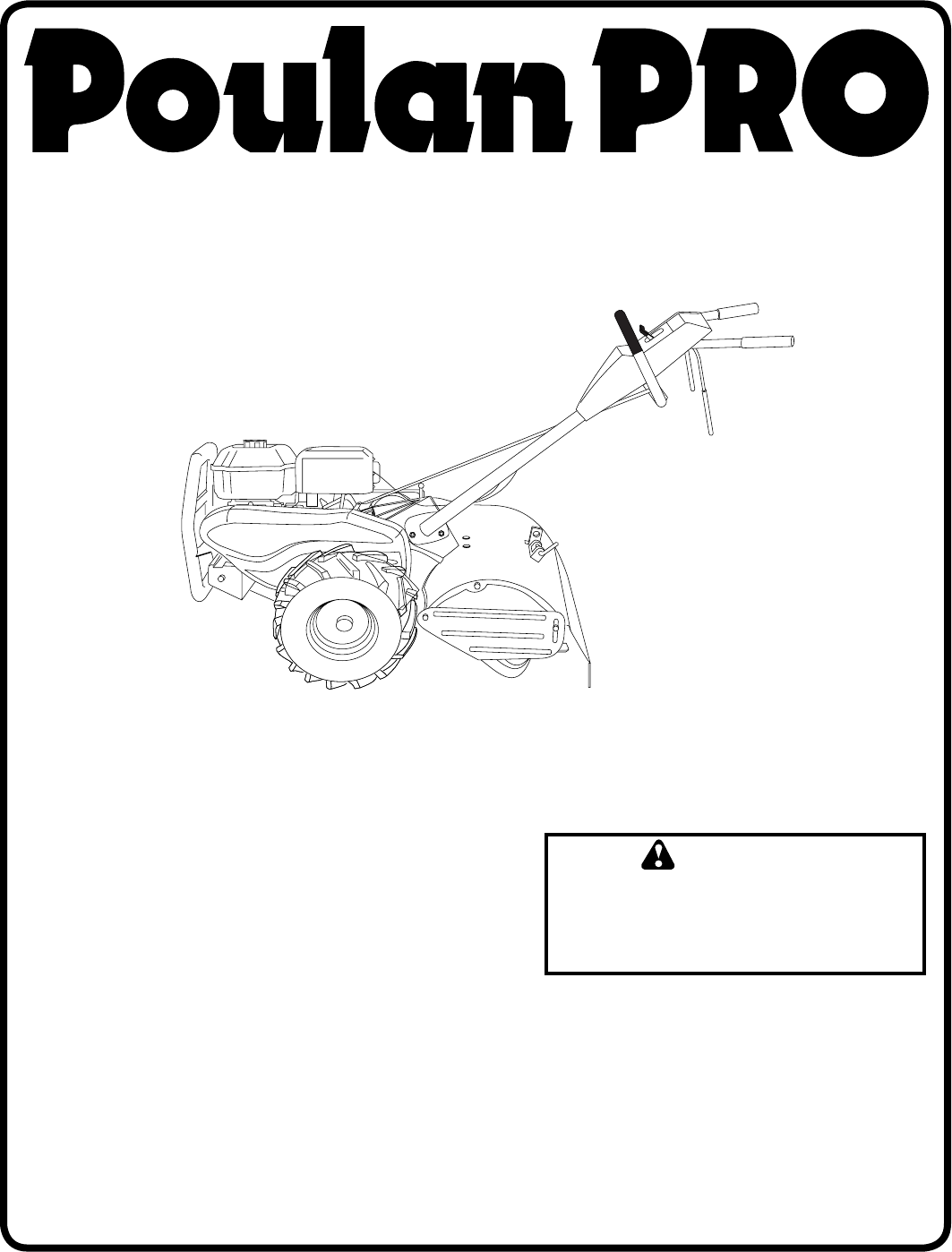
OWNER'S MANUALMODEL:PRRT65CREAR TINE TILLER ALWAYS WEAR EYE PROTECTION DURING OPERATION 184865 Rev. 1 05.13.03 TRPrinted in
10RUNCHOKEOPERATION• Soil conditions are important for proper tilling. Tines will not readily penetrate dry, hard soil which may con trib ute to
11MAINTENANCEGENERAL RECOMMENDATIONSThe warranty on this tiller does not cover items that have been subjected to operator abuse or negligence. To re
12MAINTENANCEOIL FILLERPLUGOIL LEVELOIL DRAINPLUGFIG. 16Disconnect spark plug wire before performing any maintenance (except car bu re tor adjustment)
13MAINTENANCEFIG. 19AIR SCREENBLOW ER HOUS INGMUFFLERDo not operate tiller without muffl er. Do not tamper with exhaust system. Damaged muffl ers or sp
14SERVICE AND ADJUSTMENTSCAUTION: Disconnect spark plug wire from spark plug and place wire where it cannot come into contact with plug.TILLERTO AD
15SERVICE AND ADJUSTMENTSCABLE CLIPSCREWDRIVECONTROLCABLEEXTENSIONSPRINGENGINEPULLEYIDLERPULLEYTRANS MIS SION PULLEYLESS TEN SION5/8"MORETEN SIO
16SERVICE AND ADJUSTMENTSFIG. 26TINE REPLACEMENT (See Figs. 24, 25, and 26)CAUTION: Tines are sharp. Wear gloves or other protection when han-
17SERVICE AND ADJUSTMENTSFIG. 27THROTTLE CONTROLCLAMP SCREWCASING AND WIREENGINETO ADJUST THROTTLE CONTROL CABLE (See Fig. 27)The throttle control ha
18STORAGEENGINE OILDrain oil (with engine warm) and replace with clean oil. (See “ENGINE” in the Maintenance section of this man ual).CYLINDER(S)•
19 Will not start 1. Out of fuel. 1. Fill fuel tank.
2• Never operate the tiller without proper guards, plates, or other safety protective devices in place.• Keep children and pets away.• D
20REPAIR PARTSTILLER - - MODEL NUMBER PRRT65CHANDLE ASSEMBLYKEY PART NO. NO. DESCRIPTION21 180517X428 Handle23
21KEY PART NO. NO. DESCRIPTION1 73510500 Nut, Keps 5/16-182 10040600 Washer, Lock 3/83
22KEY PART NO. NO. DESCRIPTIONKEY PART NO. NO. DESCRIPTIONREPAIR PARTSTILLER - - MOD
23KEY PART NO. NO. DESCRIPTIONNOTE: All component dimensions given in U.S. inches. 1 inch = 25.4 mm1 180677
2419 102701X Grip20 73220600 Nut, Hex 3/8-1621 102156X Stake, Depth22 74930632 Bolt, Hex 3/8-16 x
25KEY PART NO. NO. DESCRIPTIONKEY PART NO. NO. DESCRIPTION1 4459J
261 173196 Decal, CNTRL PNL 2 176306 Decal, Decal, Blt Grd4 180816 Decal, Instruction, Tilling
27LIMITED WARRANTYThe Manufacturer warrants to the original consumer purchaser that this product as manufactured is free from de-fects in materials an
Your POULAN PRO product has been expertly en gi neered and carefully manu fac tured to rigid quality stan dards. As with all mechanical products
3CONGRATULATIONS on your purchase of a new tiller. It has been designed, en gi neered and manu fac tured to give you the best pos sible de penda bil i
4TOOLS REQUIRED FOR ASSEMBLYA socket wrench set will make assembly easier. Standard wrench sizes are listed.(1) Utility knife(1) Tire pressure gauge(
5ASSEMBLY• Grasp handle assembly. Hold in “up” position. Be sure handle lock remains in gearcase notch. Slide handle assembly into position.HA
6ASSEMBLYSHIFTRODHAIRPINCLIPSHIFTLEVERINDICATORREMOVE TILLER FROM CRATE• Make sure shift lever indicator is in “N” position (See Fig. 7)• Til
7KNOW YOUR TILLERREAD THIS OWNER'S MANUAL AND SAFETY RULES BEFORE OPERATING YOUR TILLER.Compare the illustrations with your tiller to familiarize
8TURNING• Release the drive control bar.• Move throttle control to “SLOW” position.• Place shift lever indicator in “F” (forward) po
9OPERATIONOIL LEVELFIG. 12BEFORE START ING ENGINEIMPORTANT: BE VERY CAREFUL NOT TO ALLOW DIRT TO ENTER THE ENGINE WHEN CHECKING OR ADDING OIL OR FUEL
Produits connexes et manuels pour Matériel de jardinage Poulan 184865
 (24 pages)
 (16 pages)
© 2020, manymanuals.fr. Tous droits réservés | 2.503 s |
 Manymanuals.com
 Manymanuals.de
 Manymanuals.fr
 Manymanuals.it
 Manymanuals.pl
 Manymanuals.cz
 Manymanuals.es
 Manymanuals-pt.com
Commentaires sur ces manuels